Here are whole unit summary notes to help you prepare for the unit test next week.
Thanks to Mr Noble for sharing his notes.

E-Book PDF: Open in New Window | Download
with mr mackenzie

Here are whole unit summary notes to help you prepare for the unit test next week.
Thanks to Mr Noble for sharing his notes.
E-Book PDF: Open in New Window | Download
Here are some revision notes on waves to help you prepare for the unit 3 test next week.
E-Book PDF: Open in New Window | Download
Here are some notes to help with your revision for the electricity & energy test.
Thanks to Mr Noble for sharing his notes.
There are also practice exam questions and answers if you want them.
E-Book PDF: Open in New Window | Download
Thanks to Mr Ferguson for sharing his copy of the marking instructions for the 1996 Higher paper, it’s the only one I didn’t have! You’ll find a link to his answers on the Higher revision page.
Remember that your unit assessment for P&W will take place at the end of this week. The attached notes might be helpful during your revision.
E-Book PDF: Open in New Window | Download
An electric field can be used to accelerate charged particles.
Conservation of energy tells us that
work done by the electric field = change in the particle’s kinetic energy
The speed of the particle can be determined if its charge and the accelerating voltage (potential difference) are known. The notes attached to the end of this post will show how to perform the calculation.
These short video clips show how to draw electric field lines for point charges and parallel plates, with example calculations for the work done by electric fields and the final speed of charged particles in electric fields.
Q1(a) Electric fields lines around point charges from mr mackenzie on Vimeo.
Q1b – Electric field between parallel plates from mr mackenzie on Vimeo.
Q2 – Work done in moving a charged particle through a potential difference from mr mackenzie on Vimeo.
Q3 – Calculating the speed of a charged particle in an electric field from mr mackenzie on Vimeo.
E-Book PDF: Open in New Window | Download
At the end of Our Dynamic Universe, we considered big things like stars, galaxies and the Universe itself. Now the Particles and Waves unit brings us to particles so small we need groups of them just to make a single atom. Is there a connection?
An elementary (or fundamental) particle is a particle that is not built from other, smaller particles. Until the start of the 20th century, scientists had believed that atoms were elementary particles. However, the discovery of the electron (J.J. Thompson), proton (Rutherford), and neutron (Chadwick), together with Rutherford’s evidence for a heavy, positively charged nucleus at the centre of the atom suggested the atom was not an elementary particle after all.
Brian Cox explains in this video clip…
To go further, we have to introduce some particle physics vocabulary.
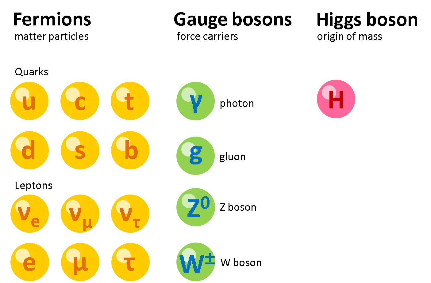
These new elementary particles are part of our Standard Model of how the building blocks of the universe interact with one another. The particles that form “matter” are called fermions, after Enrico Fermi (Fermi has an incredibly long list of things named after him). The fermions are divided into two groups; quarks and leptons, as shown in the diagram below.
The Scholar tutorial is on Monday 14th November, starting at 6pm. You can join the room from 5.30pm using the link on this page.
Twinkle, twinkle little star,
How I wonder what you are.
Giant thermonuclear reaction;
Held by gravitational attraction.
Twinkle, twinkle little star,
You look so small ’cause you’re so far.As you burn through constant fusion,
Your twinkle’s just an optical illusion.
That happens when your light gets near;
distorted by our atmosphere.
Twinkle, twinkle little star,
spreading light and heat so far.As you use up fuel you’ll grow,
and give off a scarlet glow;
Maybe you’ll go supernova,
exploding elements all over.
Now I know just what you are;
and I know I’m made of stars.
Where does the Sun get its energy? A straightforward question but physicists struggled to find an answer until the 1920s, when Eddington suggested that nuclear fusion might be responsible.
A star is drawing on some vast reservoir of energy by means unknown to us. This reservoir can scarcely be other than the subatomic energy which, it is known exists abundantly in all matter; we sometimes dream that man will one day learn how to release it and use it for his service. The store is well nigh inexhaustible, if only it could be tapped. There is sufficient in the Sun to maintain its output of heat for 15 billion years. — Sir Arthur Stanley Eddington
Our Sun is a typical yellow star, so its emission would be represented by the middle star in this image.

The colour of a star also tells us something about the expected behaviour of a star, it’s lifetime, and destiny. This is achieved by plotting stars on a Hertzsprung-Russell diagram. More about HR diagrams here.
This video clip looks at how the stars are arranged on the HR diagram.
Hertzsprung Russell diagram from mr mackenzie on Vimeo.
While some HR diagrams use temperature along the x-axis, others use star classification.