charged particles in magnetic fields

These Bitesize pages will help if you need to recap on the basics of magnets.  A magnetic field is produced whenever current flows through a wire.  The magnetic field is represented by a series of concentric circles around the wire, as shown below.

Magnetic field lines around a current carrying wire.  image: physick wiki

The direction of the arrows on these magnetic field lines is found using a left hand rule:

Point your thumb in the direction of electron flow, then wrap your fingers around the wire.  The direction in which your fingers curl is the same as the arrow direction.

A charged particle will experience a force as it moves through a magnetic field – apart from the special case where the particle enters parallel to the magnetic field lines.  There are different ways to determine the direction of the force acting on the charged particle.  The following method works for negatively charged particles.

Hold out your right hand and make a fist like Batman.…BIF!

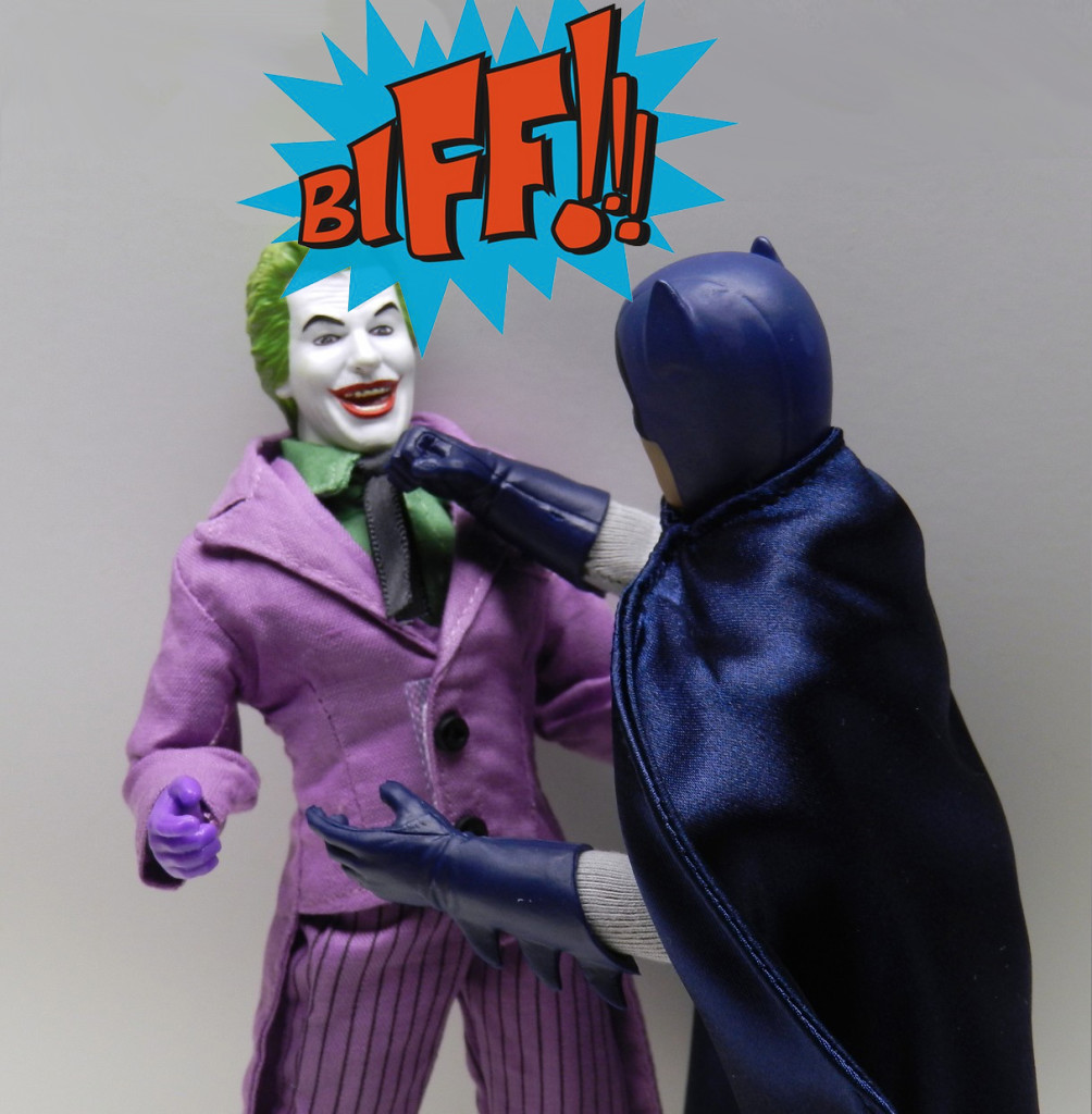
Batman making a fist with his right hand. image: infinitehollywood.com

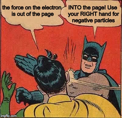
Still thinking about BIF…

  1. Straighten your thumb (B), first finger (I), and middle finger (F) so they are at 90 degrees to one another, like the x,y,z axes on a graph.
  2. Align your thumb so it points in the same direction as the arrows on the magnetic field lines (B).
  3. Rotate your right hand until the first finger direction matches the path of the negative particle (I).
  4. Your middle finger will reveal the direction in which magnetic force (F) acts on the negative particle.

if no field lines are shown, position your thumb so it points from N to S in the magnetic field

If you’ve done everything correctly, the fingers of your right hand will look like this.

Right Hand Rule

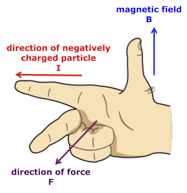
Right hand rule for negatively charged particles in a magnetic field.

If you are working with positive particles, there are two options:

  1. use your left hand instead of the right, keeping the same BIF order for the fingers OR
  2. use the right hand rule described above but reverse the direction of the force at the end.

Try both methods and decide which is best for you.
If you opt to use different hands, make sure you know which hand to use for each type of charge.

Why do we use B as the symbol for magnetic fields?  I have no idea, but there are some suggestions here.

particles in electric fields

An electric field can be used to accelerate charged particles.  Conservation of energy tells us that the work done by the field is equal to the change in the particle’s kinetic energy.  The speed of the particle can be determined if its charge and the accelerating voltage are known.  These notes show how to perform the calculation.

These short video clips show how to draw electric field lines for point charges and parallel plates, with example calculations for the work done by electric fields and the final speed of charged particles in electric fields.

Q1(a) Electric fields lines around point charges from mr mackenzie on Vimeo.

Q1b – Electric field between parallel plates from mr mackenzie on Vimeo.

Q2 – Work done in moving a charged particle through a potential difference from mr mackenzie on Vimeo.

Q3 – Calculating the speed of a charged particle in an electric field from mr mackenzie on Vimeo.

fundamental particles: quarks, leptons and the standard model

At the end of Our Dynamic Universe, we considered big things like stars, galaxies and the Universe itself.  Now the Particles and Waves unit brings us to particles so small we need groups of them just to make a single atom.  Is there a connection?


Why do we study particles? from mr mackenzie on Vimeo.
 

The Standard Model

An elementary (or fundamental) particle is a particle that is not built from other, smaller particles.  Until the start of the 20th century, scientists had believed that atoms were elementary particles.  However, the discovery of the electron (J.J. Thompson), proton (Rutherford), and neutron (Chadwick), together with Rutherford’s evidence for a heavy, positively charged nucleus at the centre of the atom suggested the atom was not an elementary particle after all.

Brian Cox explains in this video clip…

Read more

school closure work for Higher class

We’ve been looking at the photoelectric effect this week.  In this video, Professor Dave reviews some of the points we covered in class.

Click on the picture below to download a simulation to investigate the effect of irradiance on frequency on photocurrent.  You’ll be prompted to install Java if you don’t have it already.

Once the animation is running, you can;

  • change the metal under investigation (we used zinc in class)
  • vary the wavelength of the incident light
  • vary the irradiance of the incident light.

Notice that below the theshold frequency you can’t get any photoelectrons, even if you set the light to its brightest setting.

Compare your results to the graphs provided in your notes.

I have attached some notes & questions on the photoelectric effect. Click on the link below to download a copy.

particle accelerators

An electric field can be used to accelerate charged particles.

Conservation of energy tells us that

work done by the electric field = change in the particle’s kinetic energy

The speed of the particle can be determined if its charge and the accelerating voltage (potential difference) are known.  The notes attached to the end of this post will show how to perform the calculation.

These short video clips show how to draw electric field lines for point charges and parallel plates, with example calculations for the work done by electric fields and the final speed of charged particles in electric fields.

Q1(a) Electric fields lines around point charges from mr mackenzie on Vimeo.

Q1b – Electric field between parallel plates from mr mackenzie on Vimeo.

Q2 – Work done in moving a charged particle through a potential difference from mr mackenzie on Vimeo.

Q3 – Calculating the speed of a charged particle in an electric field from mr mackenzie on Vimeo.

quarks, leptons and antimatter

At the end of Our Dynamic Universe, we considered big things like stars, galaxies and the Universe itself.  Now the Particles and Waves unit brings us to particles so small we need groups of them just to make a single atom.  Is there a connection?


Why do we study particles? from mr mackenzie on Vimeo.
 

The Standard Model

An elementary (or fundamental) particle is a particle that is not built from other, smaller particles.  Until the start of the 20th century, scientists had believed that atoms were elementary particles.  However, the discovery of the electron (J.J. Thompson), proton (Rutherford), and neutron (Chadwick), together with Rutherford’s evidence for a heavy, positively charged nucleus at the centre of the atom suggested the atom was not an elementary particle after all.

Brian Cox explains in this video clip…

To go further, we have to introduce some particle physics vocabulary.

These new elementary particles are part of our Standard Model of how the building blocks of the universe interact with one another.  The particles that form “matter” are called fermions, after Enrico Fermi  (Fermi has an incredibly long list of things named after him).  The fermions are divided into two groups; quarks and leptons, as shown in the diagram below.

standard model


The Standard Model of Particle Physics. image: The University of Tokyo

Read more

refraction, critical angle and total internal reflection

We met refraction during the National 5 course.  At Higher level, we are interested in the relationship between the angles of incidence θi and refraction θr.

Snell’s law tells us that

n_1\sin \theta_i = n_2 \sin \theta_r

Usually material 1 is air, and so n_1 = 1
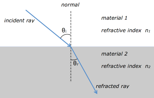
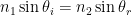
.  This simplifies Snell’s law to

\sin \theta_i = n \sin \theta_r

where n is the absolute refractive index of material 2.  Since the refractive index is equal to the ratio of the ray’s speed v in materials 1 & 2 and also equal to the ratio of the wave’s wavelength λ in materials 1 & 2, we can show that

 n = \displaystyle {{{\sin \theta_i} \over  {\sin \theta_r}}} = \displaystyle {v_1 \over v_2} = \displaystyle {\lambda_1 \over \lambda_2}

Read more about Snells’s law here.

total internal reflection

total internal reflection from mr mackenzie on Vimeo.
The critical angle \theta_c 
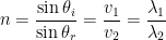
and refractive index n are related by

\sin \theta_c = \displaystyle {1 \over n }

Here are some applications of total internal reflection here.  You can test your knowledge of refraction with this interactive simulation.

I have attached a pdf with some notes and questions on refraction, total internal reflection and critical angle.

diffraction

Diffraction of a red Laser beam with a diffraction grating

red laser beam passing through a diffraction grating. image: en.academic.ru

Diffraction is a test for wave behaviour.  When a ray of light passes through a diffraction grating, the energy of the incident beam is split into a series of interference fringes.  Constructive interference is occurring at each location where a fringe (or spot) is observed because the rays are in phase when they arrive at these points.

diffraction spots projected on to a wall

image: microscopy uk

Find out about diffraction gratings here.

image: laserpointerforums.com

We can measure the relative positions of the fringes in a diffraction pattern to determine the wavelength of the light used.  The diffraction grating equation is

m \lambda = d \sin \theta

where

  • m is the diffracted order  –  some resources may use n instead of m
  • λ is the wavelength
  • d is the line spacing.

Here is an infrared diffraction experiment you can try at home to calculate the wavelength of the infrared LED in a remote control.

I’ve attached a set of pdf notes and questions on diffraction.  These notes use n rather than m for the diffracted order.

the photoelectric effect

We learned about the photoelectric effect this week.  This video has a similar demonstration to the gold leaf electroscope experiment I showed you in class and includes an explanation of the process.


Click on the picture below to download the simulation we used to investigate the effect of irradiance on frequency on photocurrent.  You’ll be prompted to install Java if you don’t have it already.

Once the animation is running, you can;

  • change the metal under investigation (we used zinc in class)
  • vary the wavelength of the incident light
  • vary the irradiance of the incident light.

Notice that below the threshold frequency you can’t get any photoelectrons, even if you set the light to its brightest setting.

Compare your results to the graphs provided in your notes.

I have attached some notes & questions on the photoelectric effect. Click on the link below to download a copy.